Gazeeka Model 870i Service Guide
Version 2024
Definitions
Parts Breakdown

Serial Number & Drawing Lookup
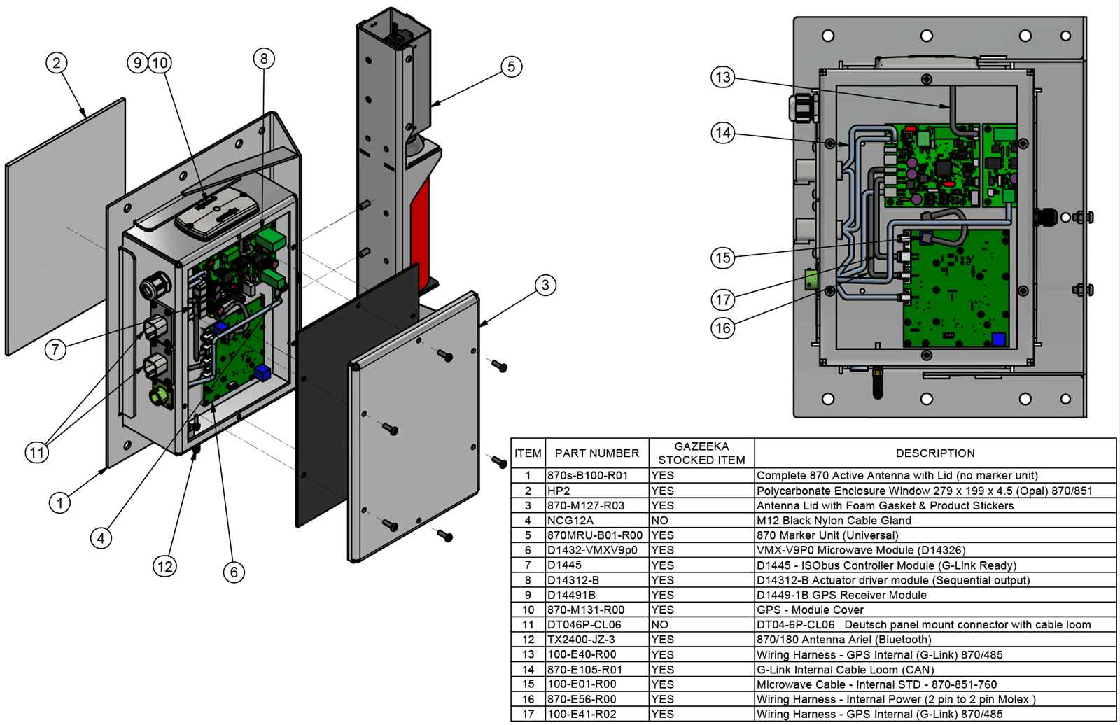
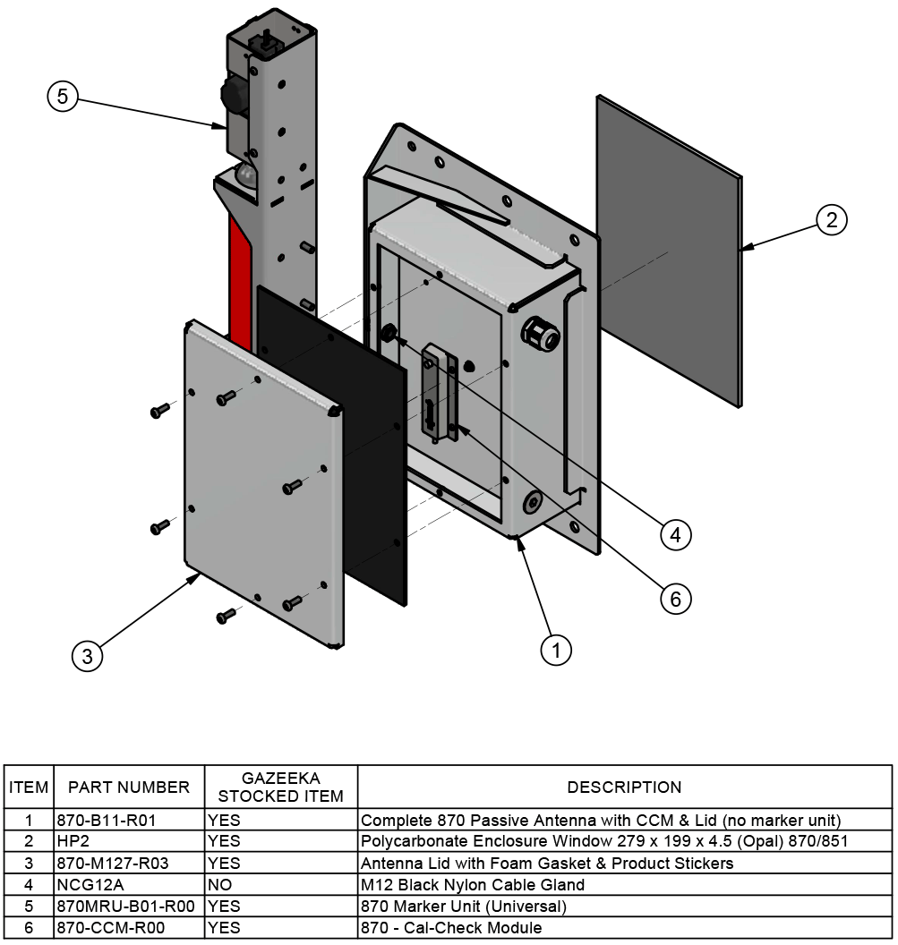
This PDF is essential for establishing the year of manufacture and the compatible components. It will also help to cross reference the wiring.
First you will need to get the serial number of the instrument. This is found inside the active antenna, located on a white sticker in the top left corner, on the wall of the antenna and will read in black writing S/N XXXX.
Once you have the serial number of the instrument, you can go to the contents of the PDF document and select the serial range it falls in and that will take you to the applicable drawing within the document.
This PDF is available to download from the documentation section on the Vomax website.
Icon Legend

Error Messages
This is most likely caused by one of the following:
- A connector has popped out/pins not seated correctly inside connector (inside the Active Antenna – left-hand side) or,
- A faulty Baler Harness or connector in the Baler Harness (connection between the ISOBUS terminal and the Gazeeka electronics) or,
- A faulty Control Module in the Active Antenna (typically, no LEDs flashing).
- Incorrectly wired internally (looking for RS422 signal not CAN).
- Not terminated correctly.
Troubleshooting Process
Power on the Gazeeka and take the lid off the Active Antenna.
- No LEDs flashing
- No power
- Check the two pin power connector (shown below) that comes in from the side of the antenna and into the bottom board (Microwave Module). There is a chance that the connector itself has popped out, or more likely that the pins are not seated correctly in the connector. If the latter is true, use a pair of pointy-nose pliers to correctly seat pins.
- Use a multimeter to measure the voltage across the same pins where they are soldered to the Microwave Module, to verify that no power is present.
- If the above checks out, the Baler Harness (ISOBUS) may need to be repaired (see the section below and the Harness Configurations section of this guide) or replaced.
- Trace the entire length of the Baler Harness to find where the potential issue is coming from (likely crushed or pinched somewhere) or use the harness tester in the Gazeeka First Aid Kit (870s-AID-R01).
- No power

- Green LED flashing on Microwave Module and red LEDs flashing on Control Module
- Check that the 4pin Molex communications connector is plugged into CAN port (not RS422 port) as shown below.
- Make sure the 4-pin Molex connector is securely clipped into place, with the pins properly seated inside the connector.
- If the above appears correct, there may be a faulty communication connection through the Baler Harness. The harness should be repaired (refer to the section below and the Harness Configurations section of this guide) or replaced.

- Check that the Baler Harness has been correctly terminated (see installation guides for more detail) and ensure terminator isn’t faulty
- Green LED flashing on the Microwave Module only
- Check the two pin harness that runs between the two boards (connectors may have popped out or pins not seated correctly).
- If the above harness seems ok, check voltage at either ends of this harness (measure where the pins are soldered to the boards – careful not to create a short).
- If there is good voltage at the top board (Control Module), it is likely a failed Control Module and you’ll need to replace this board. See the Replacing Modules section of this guide.

Repair Notes:
If an electrical cable is suspected of being faulty, it needs to be tested before any other components are replaced. A shorted-out cable is capable of potentially destroying any replacement module, thus compounding the issue.
If you suspect a cable fault, use a new cable and lay it around the hay baler and connect it in at both ends (baler ISObus port and Gazeeka instrument at the rear of the baler). Power up and if this works OK, replace the faulty baler cable. If this does not power up and work OK, then commence replacing modules in the antenna still using the test cable until the system is OK. To determine which component is at fault.
Testing a cable with connectors at each end (“belling it out”)
The following assumes the connectors are labelled A, B, C …etc. The same applies to any other labelling of a connector such as 1, 2, 3 … etc.
Testing a multi-core cable with connector on each end by testing between pins “A” on one end to pin “A” on the other end, then B, C etc. tests the continuity of the cores, but it does NOT test if any of the cores are shorted out.
To tests if cores are shorted out one needs to test between pin A on one end then B, C, D etc. (all other pins) on the other end to make sure there is NO continuity, then between pin B on the same end and pins C, D, E etc. then pin C on the same end and pins D, E, F etc. until all pins are tested against all other pins for isolation.
On all baler types ensure that the moisture system has been selected in the baler settings.
For Massey Ferguson balers there is an additional parameter that needs to be correctly selected. There was a change that was made circa 2012 that the AGCO software team made to change some of the information in the ISOBUS Name that they use to identify the Gazeeka instrument. It was easier for Gazeeka to put this setting in the software then for AGCO to try to get all their balers updated to the new Name that Gazeeka is using. With the latest machines AGCO were able to make the switch to allow for the proper Name to be used.
The setting for MF22xx should be set to “YES” for the older 2250, 2260, 2270 and 2290 balers.
The setting for MF22xx should be set to “NO” for the newer 2233, 2224, 2234 and 2244 balers.
After making the change you will need to power cycle the machine in order for the proper handshakes to occur.

The 99% error code is a generic Gazeeka error that indicates an issue with the Gazeeka operation. To resolve this, you’ll need to visit the Gazeeka page for a status update. On the “Analyse Mode” page, you may see a red error status, which will point to the specific issue. You can then refer to the “Error Messages” section of the Service Guide for further details.
The 99% error code may also appear under the following conditions:
- Not in Analyse Mode: If Gazeeka is not in the correct mode to read moisture (e.g., if it is in Setup Mode), the 99% error will appear on the baler page to notify the operator that Gazeeka is not ready to measure moisture.
- Incorrect Address (MF): For Massey Ferguson balers, if the MF22xx parameter is incorrectly set (see the “Gazeeka Moisture is Not Displaying on Baler Page” section for guidance), the 99% error code may be displayed on the bale page.
There is a good chance this is caused by a poor Air Calibration (potentially part of a bale or another form of obstruction was apparent during the Air Calibration).
Conduct a new Air Calibration, making sure there is nothing between the two antennae and they have a clear line of sight of each other. It is best practice that there is no hay within 2ft of the antenna beam.
Note: for very dry hay (less than 8%), the microwave signal will be close to the air reading signal strength. So, an occasional “No Bale” when a bale is present may occur. This just means that the hay has a very low moisture content.
If the previous steps do not resolve the issue, a factory reset may be necessary. Resetting the instrument to its original factory settings is a last resort, intended to clear any corrupted parameters after all previous troubleshooting attempts have been exhausted.
Factory Reset
- Enter the Dealer Menu
- From Analyse Mode, press the gear icon (settings)
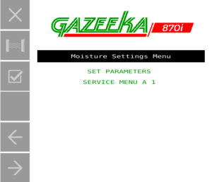
- Now select Service Menu A 1 and change the Service Code to 8001
- Press next page until you find Dealer Menu C.
- Select Enter 123 to Reset and enter 123.
- Reboot the system.
- Wait for the instrument to warm up (2 minutes) and then follow the visual step-by-step guide to setting up and calibrating your instrument in the Gazeeka Model 870i Quick Start Guide.

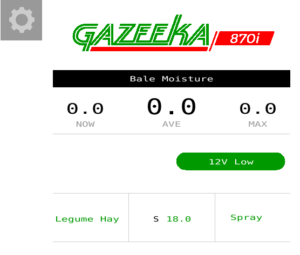
As the error code suggests, the Gazeeka system isn’t getting enough power. It is best to start at the source and work your way forward.
Troubleshooting Process
Check the baler ISOBUS harness where the Gazeeka console is getting the power from. Using a multimeter check that the power source is giving at least 13v (tractor running). If this is ok, move to the following step.
Using the multimeter, check the power is ok coming into the Gazeeka. This is done by measuring across the two-pin Molex connector (power in) on the Microwave Module (highlighted red below). This should be >13v when the tractor is running (be careful not to short this out!).


If there isn’t >13v (tractor running), there is likely an issue with Baler Harness. However, if this looks ok, then there might be an issue with the chip that measures the voltage at the Microwave Module, this can be fixed as per below.
Changing 12v Limit
- From Analyse Mode, select settings (gear icon)
- Select Service Menu A 1 and change the Service Code to 8001
- Page next until you reach Dealer Menu C
- Change 12v Limit to 11.
If this doesn’t fix the issue, the Microwave Module will need to be replaced.

This generally means that the Air Calibration values are higher than the max (attenuation > SAA Max).
Troubleshooting Process
First check for a loose or damaged Microwave Harness. This could be a kinked or crushed section of the harness. Following on from that, check the connection at either end to the antenna, this can be done by ensuring the connection is finger tight and if you gently wiggle and pull on the connection nothing comes loose.
It could also mean that a bale was still in the chamber or something obstructing the microwaves. Check that there is nothing in between the antennae, they have a clear line of sight and no hay within 2ft of faces.
Check SAA Max and Compare to MW Mode
- From Analyse Mode. select settings
- Then select Service Menu A 1 and change the Service Code to 9000
- Page next to find Tolerance Param 1 and write down the value for SAA Max (typically 35.0)
- Press the Test button
- What is the attenuation (underscored below)?

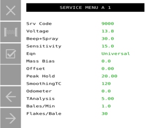
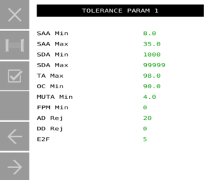

If attenuation is slightly higher (1-2) than the SAA Max (previously written down), then increase the SAA Max to just above the SAA measured through MW Mode.
Note: If the MW Mode attenuation reading (SAA) is less than 12 or greater than 50, this is a sure sign of a failed Microwave Module – this will need to be replaced. Typical readings are 18 – 23 (SAA) and 28,000 – 38,000 (SDA). This assumes that the gain values have been loaded correctly, before deciding to replace the Microwave Module check the systems gain values as per the instructions below.
Checking the gain values (v9p0 Microwave Modules ONLY – S/N 4150 – present)
Ensuring that the Microwave Module gain values are correctly loaded into the Control Module is crucial (S/N 4150 – present). Incorrect gain values can cause abnormal attenuation readings and prevent the system from passing an Air Calibration (EA Error).
Finding the gain values:
- The gain values are recorded on the Microwave Module, as shown below:

Checking the gain values:
- From Analyse Mode, select settings
- Select Service Menu A 1 and change the Service Code to 8001
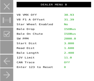
- Page next until you find Dealer Menu B
- Compare the screen values to the those written on the Microwave Module
- If they are different, you will need to overwrite them on the screen to match the board
Factory Reset
If the values from the MW Mode look ok and the gain values are loaded correctly, but the unit still wont pass an Air Calibration (EA Error) then there may be some corrupt parameters in the system. To clear the system of any corrupt parameters, a factory reset can be used.
- Enter the Dealer Menu
- From Analyse Mode, press the gear icon (settings)
- Now select Service Menu A 1 and change the Service Code to 8001
- Press page next until you find Dealer Menu C.
- Select Enter 123 to Reset and enter 123.
- Reboot the system.
- Wait for the instrument to warm up (2 minutes) and then follow the visual step-by-step guide to setting up and calibrating your instrument in the Gazeeka Model 870i Quick Start Guide
Enter the Advanced Menu (older units)
- From Analyse Mode, press the gear icon (settings)
- Now select Service Menu A 1 and change the Service Code to 9000
- Press page next until you find Service Menu B
- Select Enter 123 to Reset and enter 123.
- Reboot the system.
- Wait for the instrument to warm up (2 minutes) and then follow the visual step-by-step guide to setting up and calibrating your instrument in the Gazeeka Model 870i Quick Start Guide
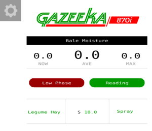
There are some model Gazeeka’s were the value of E2F needs to be increased from 500 to 9999. This spectral distortion limit was set very close to the operation limits, and in hindsight was far too low.
Changing E2F
- From Analyse Mode, select settings
- Select Service Menu A 1 and change the Service Code to 9000
- Now, page next until you find Tolerance Param 1
- Change E2F to 9999
Beyond the early model units with a low E2F value (mentioned above), this error code normally means that microwave reflections are occurring.
- Firstly, check that there is no obvious obstructions between the antennas. This could come in the way of tailgate chains running straight through the face of the antenna (note: it is ok if the chains encroach approximately 2″ into the corner of the window – but no further), tailgate is in the up position or any other metal obstructions.
- If this seems ok, check the Microwave Harness running between the two antennas for any physical damage, as a pinched, crushed or bent harness can cause reflections. It is also important to check the connections inside the antenna housings. To do this, take both lids off and check that the SMA connections are ok (gently pull/wiggle the connector to make sure it is snug and check that it is finger tight).
- If this seems ok, continue as per below.
Next we will check the Air Calibration values, making sure there was no distortion when the Air Calibration was done.
- From Analyse Mode, press settings
- Select Service Menu A 1 and change the Service Code to 9000
- Page next until you find Last Measurements 1
- What is the SDA? Shouldn’t be much higher than 30,000 (record value)
- What is the SAA? It shouldn’t be much higher than 20-30 (record value)
Now, compare the Air Calibration values to a microwave test (raw microwave readings)
- Press the Test button
- If the SAA is ok (typically 20-30) and also, the SDA is in the 20,000’s (second number) then this is acceptable
- The values should closely resemble the Air Calibration values you just recorded
- If the numbers are within the parameters just mentioned, go ahead and do a new Air Calibration
- If the SAA is ok (typically 20-30) and also, the SDA is in the 20,000’s (second number) then this is acceptable
- From Analyse Mode, select settings
- Now, press the Air Calibration button twice to begin the calibration.
- If Air Calibration fails go ahead and preform a Factory Reset (outlined below)
- If the numbers are well outside the typical numbers quoted, there is a good chance that there is an issue with the Microwave Module
- Preform a Factory Reset (outlined below). If this does not fix the issue, refer to the Replacing Modules section of this guide
Factory Reset
If the values from the MW Mode look ok and the gain values are loaded correctly, but the unit still wont pass an Air Calibration (EA Error) then there may be some corrupt parameters in the system. To clear the system of any corrupt parameters, a factory reset can be used.
- Enter the Dealer Menu
- From Analyse Mode, press the gear icon (settings)
- Now select Service Menu A 1 and change the Service Code to 8001
- Press page next until you find Dealer Menu C.
- Select Enter 123 to Reset and enter 123.
- Reboot the system.
- Wait for the instrument to warm up (2 minutes) and then follow the visual step-by-step guide to setting up and calibrating your instrument in the Gazeeka Model 870i Quick Start Guide
Enter the Advanced Menu (older units)
- From Analyse Mode, press the gear icon (settings)
- Now select Service Menu A 1 and change the Service Code to 9000
- Press page next until you find Service Menu B
- Select Enter 123 to Reset and enter 123.
- Reboot the system.
- Wait for the instrument to warm up (2 minutes) and then follow the visual step-by-step guide to setting up and calibrating your instrument in the Gazeeka Model 870i Quick Start Guide
Low Attenuation per Metre (Low APM) usually indicates that the hay is too dry to give a reasonable moisture reading (<8%). In some instances it can also occur if the Air Calibration is not good enough, or the bale is very low density and or any combination of these.
Do a new Air Calibration following the steps below:
- Make sure instrument has been on for at least 2 minutes.
- Make sure the air path between the antennae is clear (i.e., no bale, chains, tailgate or anything else obstructing the microwave path).
- Ideally, the bale chamber should be completely empty of hay or at the very least the end of the bale should be inside the rear of the baler doors by at least 200mm/1′ – no bale within 600mm/2′ of the beam.
- From Analyse Mode, press settings
- Now, press the Air Calibration button twice to begin calibration
For visual, step-by-step instructions and best practices for conducting an Air Calibration, see pages 18-19 (Air Calibration) of the Gazeeka Model 870i Quick Start Guide.
The “Reject” or “Distn” message is displayed when there are spectral distortions in the microwave signal to such an extent that we have considered this may give erroneous moisture readings.
Geometric causes: This can be caused by a number of things. Sometimes this is caused by wet and dry “layers” of hay being next to each other or unusual size “lumps” of very wet hay or the leading or trailing end of a wet bale. Often you can get this spectral distortion effect by placing your body in front of the antenna. Most times these distortions are determined by the physics and the geometry of the situation and the only resolution is to remove the cause of the distortion.
Component causes: It is also possible for an electronics fault in the microwave module to cause a spectral distortion. The microwave boards are tuned to remove internal distortion, however if the tuning screws have been tampered with (the holes in the back of the aluminum block) or a component has failed, this may cause the microwave spectrum to appear distorted and be rejected. This would be rare, and we have never seen it in the field, only when first tuning new boards at the factory.
Changing rejection values: The two parameters concerned are ADrej and DDrej (DDrej is typically zero and Drej 25 as default). Sometimes changing this value to say 30 can fix or reduce the problem, but it should not be made any larger than this.
Removing the test: You can remove this spectral distortion test by setting both “ADrej” and “DDrej” to zero. However, we do not like doing this, but if the end user believes that there are no anomalous readings being caused when this is done, then this could be a solution.
Note: If an “OV RANGE” or a “HI MOIST” situation occurs, then the cans should spray each time this is detected, but will not overwrite the alarm indication message with the word “marking” (or “spraying” on older units) as it would normally do.
However, if the “Spray On” value is set to “No” (or “Beep and Spray” value is set to 00.0 on older units), then the cans will never spray, even if an “OV RANGE” or a “HI MOIST” situation occurs.
If you are experiencing suspected spectral distortions in the microwave signal, it is suggested that you open a Support Ticket with the technical support team.
In Gazeeka units 2015 on, the Control Module does all the processing using the microwave data sent from the Microwave Module. If the communications between the two modules is lost, the system will display “No Comms”.
Troubleshooting Process
- Power up the Gazeeka and take the lid off the Active Antenna
- Check the harness between the two modules. Make sure the connectors are firmly plugged in and the pins are seated correctly.
- Gently tug on all the wires where they enter the molex connector to ensure they the pins are well crimped.
- Look to see if the Control Module LEDs are flashing, if they are and the Microwave Module LEDs are not, this would indicate a dead Microwave Module.
- Note: this assumes that power is ok (see the “No Connection” section of Error Messages for instructions on checking power)
- If the Microwave Module LEDs are flashing and the Control Module LEDs are not, then it may be a dead Control Module
- Note: this assumes that power is ok (see the “No Connection” section of Error Messages for instructions on checking power)
- Check the harness between the two modules. Make sure the connectors are firmly plugged in and the pins are seated correctly.
Note: “No Comms” will also occur if a replacement Microwave Module is put in that does not have compatible operating software (see the “Replacing Modules” section of this guide).
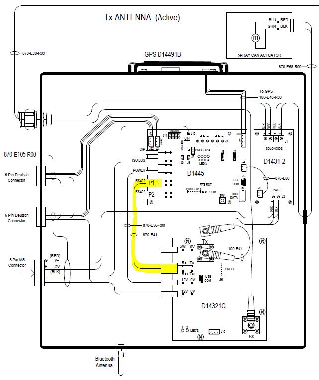

If you are using an Optical or Bale Drop sensor input to the Gazeeka, then it could be a failed sensor or a damaged harness that is causing the “Waiting” message. Take the lid off the Active Antenna and check that the sensor is correctly connected to the Control Module.
“Wait” could also mean there is a corrupt parameter in the systems memory, so if the above does not fix the issue, there may be a requirement to do a factory reset. Resetting the instrument to its original factory settings is a last resort, intended to clear any corrupted parameters after all previous troubleshooting attempts have been exhausted.
Factory Reset
- Enter the Dealer Menu
- From Analyse Mode, press the gear icon (settings)
- Now select Service Menu A 1 and change the Service Code to 8001
- Press next page until you find Dealer Menu C.
- Select Enter 123 to Reset and enter 123.
- Reboot the system.
- Wait for the instrument to warm up (2 minutes) and then follow the visual step-by-step guide to setting up and calibrating your instrument in the Gazeeka Model 870i Quick Start Guide.
Whenever the system is running, a periodic test is done on the non-volatile memory. It stores parameters which will not be lost when the instrument is switched off. If this memory fails then the instrument may not calculate the microwave signal or the moisture value correctly. The only solution to this is to replace the microwave module.
Note that we do not test all of the memory locations, so it is possible to have a memory failure without the “Memory Failure” message coming up. Memory failure can appear in various ways, with one common manifestation being parameter corruption. While clearing corrupt parameters can temporarily resolve the issue, the fix is typically temporary, and corrupt parameters may reoccur in the operating system.
If memory failure is suspected, clearing the corrupt parameters may be the only solution, necessitating a factory reset. To reset the instrument to its original factory settings and attempt to clear any corrupted parameters should be reserved for ’emergency’ situations, only after all prior troubleshooting steps have failed. It is recommended that any factory resets be performed by a certified Gazeeka technician.
Alternatively, please contact our Support Team for assistance.
Factory Reset
- Enter the Dealer Menu
- From Analyse Mode, press the gear icon (settings)
- Now select Service Menu A 1 and change the Service Code to 8001
- Press page next until you find Dealer Menu C.
- Select Enter 123 to Reset and enter 123.
- Reboot the system.
- Wait for the instrument to warm up (2 minutes) and then follow the visual step-by-step guide to setting up and calibrating your instrument in the Gazeeka Model 870i Quick Start Guide
Enter the Advanced Menu (older units)
- From Analyse Mode, press the gear icon (settings)
- Now select Service Menu A 1 and change the Service Code to 9000
- Press page next until you find Service Menu B
- Select Enter 123 to Reset and enter 123.
- Reboot the system.
- Wait for the instrument to warm up (2 minutes) and then follow the visual step-by-step guide to setting up and calibrating your instrument in the Gazeeka Model 870i Quick Start Guide
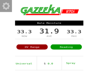
OV Range = Over Range which means the microwave signal that is being measured is weaker than the limits we have set internally.
Assuming the system is not trying to measure very high moisture hay (e.g. balage/halage) and there is no physical damage to the antennae, this could be caused by a broken Microwave Harness or a faulty Microwave Module.
Initially check the antennae have not been knocked or damaged. If using break-away brackets, ensure that the antennae are correctly positioned so they are facing each other. Next, check the Microwave Harness for any obvious damage. This could be a kinked or crushed section of the harness. Following on from that, check the connection at either end to the antenna, this can be done by ensuring the connection is finger tight and if you gently wiggle and pull on the connection nothing comes loose.
Unlikely, but a memory corruption could cause this. So, if the above does not fix the issue there may be a requirement to do a factory reset. To reset the instrument to its original factory settings and attempt to clear any corrupted parameters, this action should be reserved for ’emergency’ situations, only after all prior troubleshooting steps have failed. It is recommended that any factory resets be performed by a certified Gazeeka technician.
Alternatively, please contact our support team for assistance.
Factory Reset
- Enter the Dealer Menu
- From Analyse Mode, press the gear icon (settings)
- Now select Service Menu A 1 and change the Service Code to 8001
- Press page next until you find Dealer Menu C.
- Select Enter 123 to Reset and enter 123.
- Reboot the system.
- Wait for the instrument to warm up (2 minutes) and then follow the visual step-by-step guide to setting up and calibrating your instrument in the Gazeeka Model 870i Quick Start Guide
After setting the instrument back up, check that it passes an Air Calibration.
If the Air Calibration is OK, disconnect the Microwave Harness in the right-hand antenna and let it hang loose. There will be a weak signal still getting through just like a very high moisture bale. If an error message comes up (like a phase error) or a moisture reading above 26%, then the microwave system is reading well at both ends of the scale. Reconnect the Microwave Harness.
If the above does not fix the issue, the Microwave Module needs replacing. Refer to the “Replacing Modules” section of this guide.
Marker Units
All Gazeeka marking systems serial number 2501 on use a Marker Module (D1431-2) which drives the markers separately. There are three LEDs which light up on this module when the marking system is operated. D4 (next to the jumper harness between the Control Module and Marker Module) lights up red when the marking system is operated, this determines that communications between the two boards is ok. D5 (green LED under left hand side marker terminals) determines if the left side is working or not and D6 (green LED under right had side marker terminals) determines the right.
A lot of the time the system not marking comes down to the can. Make sure you clean any loose matter out from under the cap, put felt washer supplied under cap and then check that the spray can is easily sprayed by hand. If the can is not easily sprayed by hand, the actuator will struggle to fire the paint.
If the above seems ok, but the cans are still not working, continue onto the next section.
Initial checks:
- If this is a G-Link model (2023 or newer) make sure that the power for the markers is correctly connected in the tractor cab. On the baler loom, there is a connector junction with 3 leads. One is the round connector that plugs into the bottom of the Gazeeka terminal, the other 2 pin connectors are labelled terminal power and tractor power. Plug the lead coming out of the terminal into the terminal power 2 pin connector and then plug the power from the tractor into the tractor power connector.
- Inside the active antenna (left-hand side), make sure that the marker units are connected correctly and that all the other connections are correctly seated. If an issue is found here, rectify the issued and than use the toggle button on the control board to test markers again (SW1 – circled in red below).
If the above seems ok, there is likely to be a power issue or a failed marker driver module. Press the toggle button SW1 (circled red below – this is at the bottom of the board on newer models) on the control module and check that the D4 LED lights up red. This is the LED next to the communications loom that jumps between each board (870-E80), if this lights up, then the two boards are communicating with each other. Now press the toggle button and check that the D5 & D6 LEDs on the marker driver module light up green. If D4 lights up, but neither D5 & D6 light up, check that there is adequate voltage being supplied to the marker driver module. Grab a mulimeter and measure the voltage at the power in terminal (circled green below). If there isn’t 12v here, then there is an issue with the supply of power. Trace the internal loom and then baler loom (antenna to terminal) to find the issue. Steps for this can be found in the “Error Messages” section under “No Connection”.
If the voltage is ok at the power in terminal for the marker driver module and the markers still don’t work, test each marker by putting a 12v supply straight to it and seeing whether it actuates or not. Disconnect the red and black wires from the marker control board (circled yellow below) for the actuator you wish to test and connect 12v supply correctly orientated. If they don’t plunge, then the actuator has failed and needs replacing.
If all of the above seems ok, then there is a high chance that the marker driver module has failed. Replace module (D14312-B).

Conduct above check (“Both Spray Cans are not Working” – previous section) to ensure that LEDs come on, for both the left and right-side markers. If this is the case and still only one can is marking, check the can operates manually as per previous section. If can seems ok, it is likely the actuator has failed – replace failed actuator.
The D1431-2 Driver drives each marker separately. Therefore, one can swap the two pairs of black and red wires over to see if the problem follows the wiring. If the other marker fails, then it is the electronics at fault. If the same marker fails, then the problem is with that maker unit.
Moisture Readings
How it Works
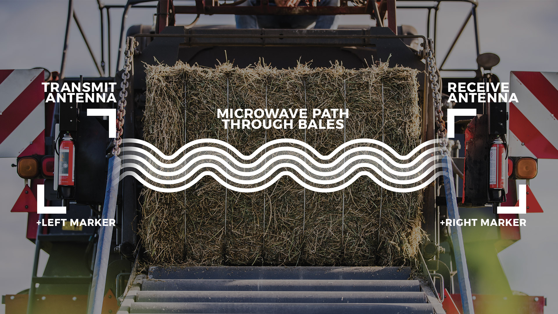
Gazeeka instruments use microwaves to measure moisture in hay bales. These microwaves move through the hay at different speeds depending on how much moisture is present. Dry hay slows the microwaves slightly compared to air, but water slows them much more. The instrument measures how fast the microwaves travel through the bale and how much energy they absorb. Gazeeka has engineered advanced hardware and software to transmit, receive and analyse these signals, thereby providing precise moisture readings for hay bales.
When a bale enters the microwave beam, the system detects its presence and monitors changes in the microwave signal to determine movement. It waits until the bale has sufficiently passed through the beam before converting microwave readings into moisture content. This ensures that the entire detected microwave signal has travelled through the bale and not some of the single going around the end of the bale.
For reliable moisture measurement, three key factors are crucial: a good air calibration, correct bale width setting, and selecting the right equation for the type of hay. Once set, the first two factors typically remain stable unless the baler or microwave system undergoes significant changes. In newer models, entering the approximate size and weight of the hay bale further enhances measurement accuracy by considering its bulk density.
Not all microwave moisture sensors are built the same. It’s crucial that the microwave technology have sophisticated software and hardware that will last from one baler to the next.
Understanding the Limitations of the Readings
Comparing with Other Moisture Measurement Methods:
Other methods, like conductivity, are sometimes used to measure moisture in hay bales. These methods might give different readings compared to the Gazeeka instrument. While these alternatives may not be as precise as the Gazeeka, they could be the standard for payment or the method you’ve used previously. It’s important to acknowledge these differences until you’re confident in your new Gazeeka instrument.
For cured legume and cereal crops, evidence suggests conductivity readings will read several points higher than the microwave system. However, over a few days, conductivity readings tend to align more closely with the Gazeeka readings taken on the day of baling. For crops that aren’t cured, the difference in readings may be more significant, and they might not converge over time.
Research indicates that conductivity methods may not provide accurate real-time measurements of bale moisture during the baling of steamed hay. This discrepancy arises because surface moisture on the hay causes conductivity readings to register several points higher than the actual moisture content. Conductivity sensors operate by seeking the path of least resistance, and surface moisture conducts more readily than the overall moisture profile of the hay being baled.
Hay Additives:
Overdosing additives can affect both microwave and conductivity methods, although conductivity methods are typically impacted more. Some hay additives, especially propionic acid, will affect the performance of the moisture readings more than others. Propionic acid, unlike most additives, requires you to increase the dose rate as the moisture content increases, leading to very high dose rates at high moistures. Typical additives on the market don’t significantly affect the performance of the Gazeeka instrument when used at recommended doses.
Hay Spoilage:
Hay spoilage or even spontaneous combustion is not caused by moisture content alone. Spoilage depends on factors like bacteria, yeast, mold levels (measured in CFU/gram), water-soluble carbohydrates (sugars), oxygen levels, and moisture content. The presence of bugs and sugar content varies with factors such as time down, seasonal conditions, cutting time and other factors. Hay is at higher risk of spoilage if cut before the plant fully matures. This will slow the drying of most types of hay and is especially noticeable when the growing season has had a dry finish (drought conditions).
These considerations are crucial for making informed decisions about when to bale and at what moisture levels, particularly for preventing spoilage and ensuring hay quality. We strongly recommend consulting the Operator’s Manual for a thorough understanding of how the system operates and its limitations. This section only provides a high level overview.
A good way to verify the moisture of your hay is through your humble microwave oven at home. It can take a few trials to become comfortable with the process, but it’s an absolute method for determining the moisture content of a sample. Please note, it is fundamental to understand the importance of representative sampling and how the sample you pulled represents a bale, windrow or field. We’ve created an easy to follow document to assist in best practice when it comes to sample collection and moisture analysis.
For reliable moisture measurement, three key factors are crucial: a good Air Calibration, correct bale width setting, and selecting the right equation for the type of hay. Once set, the first two factors typically remain stable unless the baler or microwave system undergoes significant changes. In newer models, entering the approximate size and weight of the hay bale further enhances measurement accuracy by considering its bulk density.
CHECK LIST
- Make sure the correct equation (crop type) has been selected in Analyse Mode (exert from Quick Start Guide below)
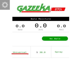

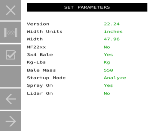
- Check all Set Parameters are entered correctly
- From Analyse Mode, press settings
- Now, select Set Parameters and
- Conduct a good Air Calibration
- Press the Air Calibration button twice to begin calibration
For visual, step-by-step instructions and best practices, see pages 23-25 (Setting Up Your Moisture Meter and Editing Instrument Parameters) and pages 30-31 (Air Calibration) of the Model 870i Quick Start Guide.
If the above is ok, enter the Dealer Menu
- From the Analyse screen
- From Analyse Mode, press settings
- Now, select Service Menu A 1 and change the Service Code to 8001
- Page next until you find Dealer Menu A
- Now check the Air Calibration values
- Use the ITEM key to find SDA (this should be around 18,000 to 30,000).
- Use the ITEM key to find SAA (this should be around 18 to 26).
- If SAA is around 40 or more, then the chances are the Air Calibration was done with a bale (or something else) either in the beam or partially in the beam. Clear the air path (no bale or anything else within 3 feet of the antenna beam) and do a new Air Calibration. If the Air Calibration is still wrong, replace the microwave module with the correct version replacement (see ‘Replacing Modules’ section of this guide).
For new users it is sometimes difficult to come to grips with the fact that we are calibrated to “oven dried moisture” which is the industry laboratory standard and not some arbitrary conductivity readings from a conductivity meter whose manufacturers may not say what it is calibrated against.
If “Version A” above does not fix the issue, there may be a requirement to do a factory reset. To reset the instrument to its original factory settings and attempt to clear any corrupted parameters, this action should be reserved for ’emergency’ situations, only after all prior troubleshooting steps have failed. It is recommended that any factory resets be performed by a certified Gazeeka technician.
Alternatively, please contact our support team for assistance.
Factory Reset
- Enter the Dealer Menu
- From Analyse Mode, press the gear icon (settings)
- Now select Service Menu A 1 and change the Service Code to 8001
- Press page next until you find Dealer Menu C.
- Select Enter 123 to Reset and enter 123.
- Reboot the system.
- Wait for the instrument to warm up (2 minutes) and then follow the visual step-by-step guide to setting up and calibrating your instrument in the Gazeeka Model 870i Quick Start Guide
Microwave Check
From Gazeeka serial number 2699 on there is a Calibration Check Module (CCM) mounted in the Passive Antenna. A description on how to use this is in the Owner’s Manual, but is repeated below for reference.
If the instrument is measuring the full dynamic range, it is highly unlikely there is anything wrong with the microwave measuring system.
In-built calibration check (V19p83 – present)
Your Gazeeka instrument has a CCM in the Passive Antenna (the one without the electronics in it on the right-hand side of the hay baler).
The combination of doing a normal Air Calibration and then a CCM check will confirm that the Microwave Module is reading the microwaves correctly across the whole dynamic range, from dry to wet hay.
A. Dry End: The Air Calibration checks that the strongest signals which are present without a hay bale being present are being read correctly.
B. Wet End: The CCM reading checks that the weakest signals which are present with a very wet hay bale being present are being read correctly. This is done by inserting the CCM into the circuit with no hay bale between the antennae and doing the test.
A. Do an Air Calibration as follows (with the tractor running):
Doing an Air Calibration is one of the most important steps when setting your Gazeeka moisture meter up for baling. This not only sets the reference point for the moisture readings, but it is also a good system check to ensure your unit is operating correctly.
Before you start:
- Make sure the instrument has been on for at least 2 minutes (tractor running)
- Make sure the air path between the antennae is clear (i.e., no bale, chains, tailgate or anything else is obstructing the microwave path)
- Ideally, the bale chamber should be completely empty of hay or at the very least the end of the bale should be inside the rear end of the baler doors and thus, no bale within 600mm/2′ of the sensors
- Air Calibration:
- From Analyse Mode, press Settings (gear icon)
- Press the Air Calibration button twice to begin the calibration
For visual, step-by-step instructions and best practices, see pages 30-31 (Air Calibration) of the Gazeeka Model 870i Quick Start Guide.
B. Do a CCM test (with the tractor running):
The steps below assume you have just done an Air Calibration as per (A) above.
Putting the CCM in the circuit:
- Take the lid off of the Passive Antenna (the one without the electronics in it on the right-hand side of the hay baler)
- Remove aerosol cans from marking units before continuing – they will spray during this test
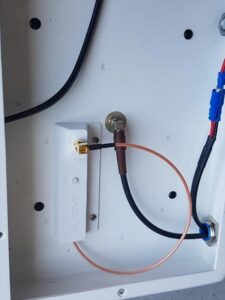
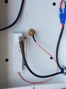
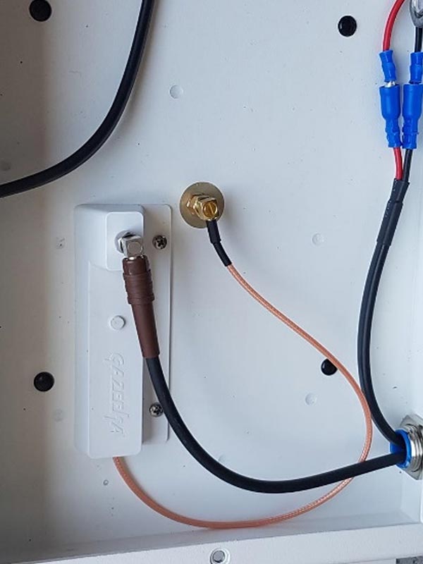
- Unscrew the Microwave Harness from the central antenna connector
- Unscrew the microwave cable on the CCM and screw it onto the central antenna connector
- Screw the Microwave Harness coming from the other antenna on the end of the Calibration Check Module (see below)

Conducting the CCM test:
Make sure the air path between the antennae is clear (i.e. no bale or anything else). The end of the bale should be inside the rear end of the baler doors by at least 2′.
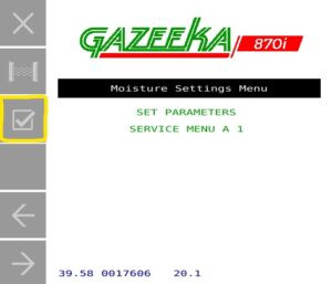
- From Analyse Mode, press Settings (gear icon)
- Now, press the Test button once (this will display the raw microwave data) > Then press Test three times in quick succession
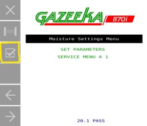
If no error message is displayed, then the following message should come on the screen “XX.X% PASSED” (XX.X% should be approximately 20% – +/- 1%). If the rest failed, it will show “XX.X% FAILED“.
Once the test has passed, disconnect the CCM and screw the Microwave Harness back into the central connector in the Passive Antenna. Put the lid back on the Passive Antenna, making sure not to tighten the fasteners too much and crush the rubber washers. Now, put your aerosol cans back in the marker units and put the unit back in Analyse Mode.
Replacing Modules
Microwave Module 7p2 no controller code – Slow interface. Obsolete and no remaining stock (v14p35)
Microwave Module 7p2 no controller code, fast interface – Was required for full spectrum analysis. Obsolete and no remaining stock (v1p06).
Microwave Module 7p2 with controller code – Obsolete and no remaining stock (v1p11).
Microwave Module 8p0 – Form fit and function compatible with 7p2 and 9p0, but different gain values.
Microwave Module 9p0 – Form fit and function compatible with 7p2 and 8p0, but different gain values.
Control Module D1394 – Replaced by Control Module D1445 plus D1431-2 marker driver.
Control Module D1400 – Replaced by Control Module D1445 plus D1431-2 marker driver.
Control Module D1431-1 – Replaced by Control Module D1445 plus D1431-2 marker driver.
Solenoid driver MC50 – replaced by D1431-2.
Notes:
- All of the 7p2 Microwave Modules can be reprogrammed in the factory to be compatible with Gazeeka 870 units up to and including 2022 models.
- The fast interface was introduced in August 2014: 7p2 version 1p06, D1394 V14p30 (wiring: 870-E40).
- The 9p0 module was designed when some electronic chips used in the 8p0 Microwave Module were no longer available during the Covid-19 pandemic.
- If you are using the D1445 plus D1431-2 to upgrade older system, then care must be taken to make sure the Microwave Module used has the fast interface.
Serial numbers Prior to 1305 and Microwave Module only units can only be repaired by replacing the 7p2 Microwave Module with a refurbished module loaded with software version 14.35.
2024 update: obsolete and no remaining stock. All units with serial numbers prior to 1305 are not serviceable and will need to be replaced with a complete new unit.
Serial number 1305 to 1540 (E57) are “hybrid units” which only use the D1394 to drive the markers. The operating code is still in the Microwave Module. Repairs could be as follows:
- Marker driver failure, replace with a new or refurbished D1394 if one is available (note the link position is different to the shipped position). If not, then full system option below.
- Microwave Module failure, replacing the 7p2 Microwave Module with a refurbished 7p2 module if one is available loaded with software version 14.35. If not, then Full system option below.
- 2024 update: 7p2 Microwave Module is obsolete and no stock remaining.
- Full system option 1. If the modules are available, Replace the D1394 with one with the latest code for that module AND replace the Microwave Module with a refurbished Microwave Module 7p2 (fast interface). If not, then full system option 2 below
- 2024 update: 7p2 Microwave Module is obsolete and no stock remaining.
- Full system option 2. Replace the D1394 with the latest D1445 and D1431-2 with the latest code and replace the Microwave Module with a new 9p0 Microwave Module.
Serial number 1541 to 2070 (E59/E40) are not compatible with 9p0 Microwave Modules. Repairs could be as follows:
- Marker driver failure, replace with a new or refurbished D1394 if one is available. If not, then full system option below.
- Microwave Module failure, replacing the 7p2 Microwave Module with a refurbished 7p2 module if one is available loaded with software version 1p11. If not, then full system option below.
- 2024 update: 7p2 Microwave Module is obsolete and no stock remaining.
- Full system option 1. If the modules are available, replace the D1394 with one with the latest code for that module and replace the Microwave Module with a refurbished microwave module 7p2 (fast interface). If not, then full system option 2 below.
- 2024 update: 7p2 Microwave Module is obsolete and no stock remaining.
- Full system option 2. Replace the D1394 with the latest D1445 and D1431-2 with the latest code and replace the Microwave Module with a new 9p0 Microwave Module.
Note: Any upgrade from a D1394 or prior (pre serial number 2071) to a D1445 and D1431-2 will require a new internal mounting bracket for the extra PCB support standoffs. The required part number is D1394-D1445. This includes a new control board (D1445), marker module (D14312), mounting plate (M118) and internal power harness.
Serial number 2071 on (year 2017)
| Serial Number | Microwave module | V8 Replacement requirements | V9 Replacement requirements |
| 2071 to 2500 (E74/E75 USA) (E40/E59 UA) | V7p2 V1p11 | Replace existing control module with a D1431-1 (or D1445 V24p00 and D1431-2) with at least V19.89 software | Replace existing control module with a D1431-1 (or D1445 V24p00 and D1431-2) with at least V19.89 software |
| 2501 to 3370 (E81/E82) | V7p2 1p11 | Upgrade software to at least V19.89 on the controller module | Upgrade software to at least V19.89 on the controller module |
| 3371 to current | V8 | Compatible | Compatible |
| Mid 2022 | V9 | Compatible | Compatible |
Please note that over the years a number of Gazeeka Model 870 instruments have been updated / upgraded (particularly in the USA) and the factory has no record of which serial numbers have been changed. It is often good practice to take a photograph of the electronics in the Active Antenna (with any version number that can be seen on a round green sticker) and send it to your dealer or create a support ticket with a clear description of the problem, make and model of baler, and your contact details.
Open a ‘Support Ticket’ here: https://db.samj.us/support/create.
| SKU | Description |
| VMX850V7p2-R-V1p11 | Refurbished Microwave Module V7p2 with V1p11 (MW only) |
| VMX850V7p2-R-V14p35 | Refurbished Microwave Module V7p2 with V14p35 (with control code) |
CHECK THE MODULE COMPATIBILITY SECTION BEFORE CONTINUING.
Equipment List
- #2 pozi drive (or Phillips head) screw driver.
- 8mm open spanner (5/16″ wrench) for SMA connectors (or fingers OK).
Procedure
- Make sure the power is off
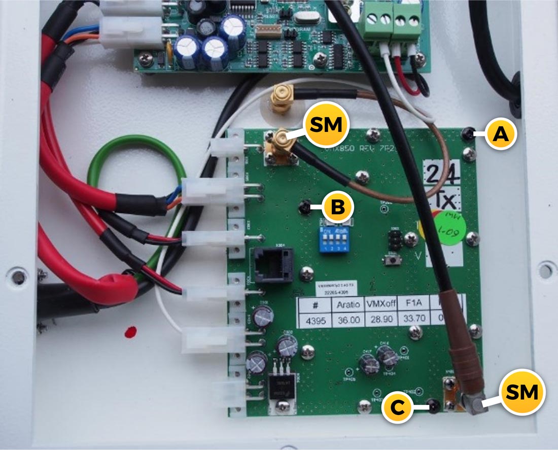
- Using the 8mm wrench (or fingers) undo the SMA (SM) connectors (two) on the Microwave Module.
- Unplug the white “Molex” connectors on the edge of the microwave board assembly, noting which ones go where. (Note: the single white wire in the 4-way connector is only present in some older version modules).
- Using a pozi drive (or Phillips head) screw driver remove screws marked A, B & C in the picture (which are typically painted black). The Microwave Module will then be free to be removed.
- To reassemble, reverse this procedure. If you are not sure which Molex connectors go where, the diagram to show which Molex connectors go where is in the Owner’s Manual. The SMA connectors should be tightened to no more than 1Nm torque. If you do not have a torque wrench, tighten as firmly as you can using your fingers (they won’t come loose). Don’t use any other mechanical means.
- Replacement complete.
Now, treat the unit like it is new and follow the visual step-by-step guide to setting up and calibrating your instrument in the Gazeeka Model 870i Quick Start Guide.
Important Tip (v9p0 Microwave Modules ONLY)
When connecting a new microwave module (v9p0 only), it is important to check that the gain values have been loaded correctly into the Control Module. This is best done after conducting the above setup and is best practice. Note, if an Air Calibration fails during the above setup procedure (EA Error), this may indicate that the Microwave Module gain values have not been loaded correctly.
Finding the gain values:
- The gain values are recorded on the Microwave Module, as shown below:

Checking the gain values:
- From Analyse Mode, select settings
- Select Service Menu A 1 and change the Service Code to 8001
- Page next until you find Dealer Menu B
- Compare the screen values to the those written on the Microwave Module
- If they are different, you will need to overwrite them on the screen to match the board
CHECK THE MODULE COMPATIBILITY SECTION BEFORE CONTINUING.
Equipment List
- #2 pozi drive (or Phillips head) screw driver.
- 8mm open spanner (5/16″ wrench) for SMA connectors (or fingers is OK).
Procedure
- Disconnect all the plugs on the board noting where each one goes.
- Unscrew the M3 screws which secure the board in place.
- Screw in the new board and replace the plugs.
- Task complete.
If required, the Active Antenna wiring diagram (870-E101-R03) can be found in the Gazeeka Model 870i Quick Start Guide (page 10).
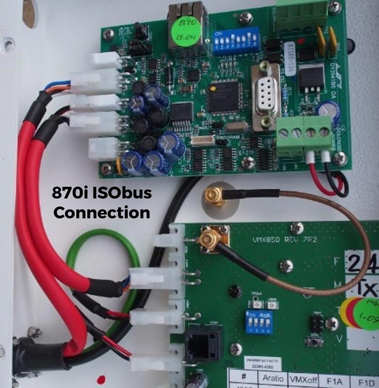
Older models: note the only internal difference between a standard 870s Gazeeka using a Gazeeka terminal and an 870i ISObus unit is the position of the 4-way connector which goes to the external harness connection (see below). Note that there are also external harness differences.

Module LED Meanings
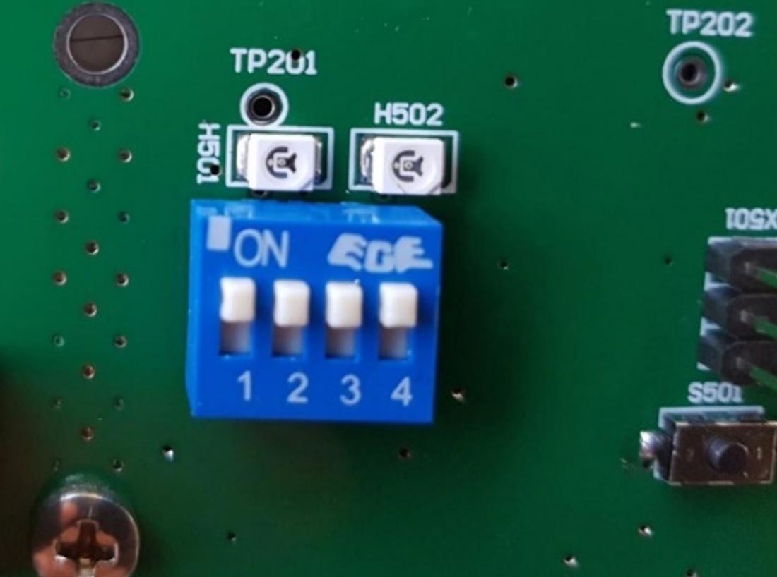
V9p0 Microwave Module LEDs
Microwave Module (V8p0/V9p0)
Firmware versions 1.xx to 2.xx (most recent)
LED H501: Blinks when powered on and operating normally
LED H502: Blinks whilst reading microwaves
Note: 1.06 was first to use high speed Baud rate to the Control Module.
Versions 1.00 to 1.05 are not compatible with current spare Control Modules.
Firmware versions 9.xx to 15.xx (older versions)
LED H501: blinks whilst reading microwaves
LED H502: Not Used
V7p2 Microwave Module: the LEDs are located above the DIP switches.
D1394 / D1400 Controller Modules
LED A: 1Hz flash all the time. If continuously ON or OFF then the code is not operating correctly.
LED B: Flashes when an ISOBUS data packet is transmitted. If 20 or more packets are sent per second, then this may appear fully on.
If no ISOBUS connections is available, this LED will continue flashing looking to see if a new ISOBUS connection is trying to be made.
LED C: Flashes when there is communication with the Microwave Module.
LED D: Flashes when bale marking is enabled.
D1431 / D1445 Controller Modules
LED A Flashes with each RS422 transmission. Goes off once an ISOBUS link is established.
LED B Flashes with ISOBUS communicating (off until the link is established).
LED C Flashes with each transmission received from the Microwave Module.
LED D Flashes on bale marking (if this does not flash when the marker push button on the D1431-1 is pressed, then this will indicate dead code).
LED ABCD All flash in sequence whilst new code is being loaded (via Bluetooth connection or USB memory stick).
Thus, if there are no connections (no RS422, ISOBUS or Microwave Module) only LED A will flash trying to communicate. This sequence is typically 3 flashes and then blank.

Updating Software & Bluetooth
Gazeeka Model 870 units from serial number 2501 on which have the D1431-1 or D14451-A Control Modules have a Bluetooth connection option.
The Bluetooth antenna is at the bottom of the Active Antenna (the one with the electronics in it). The antenna is connected via an SMA connector. To prevent damage, this antenna may be packaged separately and a rubber dust cap fitted to the SMA connector. To operate the Bluetooth connection the antenna is required to be attached.
We recommend that the lid of the antenna be removed during these operations so that the diagnostic LEDs can be viewed. This is especially true if updating software because if the link is disconnected during the uploading of new code, there is a good chance that only returning the antenna to the factory can resurrect the code.
Each of these instruments will have been loaded with a unique Bluetooth name which includes the instrument’s serial number. If the instrument has been factory reset in the field, the Bluetooth name may have reverted to a default “RN” number or “Model870-00-0000”
This Bluetooth connection can be used for the following:
- Operate the Gazeeka 870 from a device such as a Smartphone.
- Allow remote access over the internet for servicing.
- Allow remote software upgrades over the internet.
The Gazeeka Model 870 can be operated via the Bluetooth connection for servicing.
This can be done as follows:
- Download and install the app – “Model 870 Remote Control”.
- Android: In your phone Settings scan for Bluetooth devices and pair with the Gazeeka unit. The Gazeeka Bluetooth name should be “Model870-YY-Serial_Number of Device” (if the instrument has been factory reset in the field, the Bluetooth name may have reverted to an “RN” number or “Model870-00-0000”).
- Once paired with the instrument, open the “Model 870 Remote Control” app. In the top right hand corner touch the three dots and select “Connect to 870/485”. Now control access via Smartphone is active.
- iPhone, open remote control app, in the top right hand corner touch the three horizontal stripes and select “Connect to 870/485”. Scan of Bluetooth Devices will find “Model870-YY-Serial_Number of Device” (if the instrument has been factory reset in the field, the Bluetooth name may have reverted to an “RN” number or “Model870-00-0000”). Select this and now control access via iPhone is active.
The Gazeeka Model 870 can be remotely accessed when a Smartphone is connected to the unit via the Bluetooth connection and that device is connected to the internet or a WIFI network. This function allows Gazeeka technicians to remotely access your unit for troubleshooting or service needs.
This can be done as follows:
- Ensure your device is connected to the internet or a WIFI network.
- Download and install the app – “Model 870 Remote Control”.
- Android: In your phone Settings scan for Bluetooth devices and pair with the Gazeeka unit. The Gazeeka Bluetooth name should be “Model870-YY-Serial_Number of Device” (if the instrument has been factory reset in the field, the Bluetooth name may have reverted to an “RN” number or “Model870-00-0000”).
- Once paired with the instrument, open the “Model 870 Remote Control” app. In the top right hand corner touch the three dots and select “Connect to 870/485”. Jump to step 7.
- iPhone, open remote control app, in the top right hand corner touch the three horizontal stripes and select “Connect to 870/485”. Scan of Bluetooth Devices will find “Model870-YY-Serial_Number of Device” (if the instrument has been factory reset in the field, the Bluetooth name may have reverted to an “RN” number or “Model870-00-0000”).
- Once paired with the instrument, open the app. In the top right hand corner touch the three dots and select “Connect to 870”. Now control access via Smartphone is active.
- Now, select the dropdown menu in the top right-hand corner of the app, scroll down and select “Enable Remote access”.
- Remote access will now be available from a Gazeeka website for the technician to access.
- Only proceed with a software update on a Model 870 unit if advised to do so from Samuel Jackson, Incorporated.The Gazeeka Model 870 can be remotely software upgraded via the Bluetooth connection and a Smartphone connected to the internet.This can be done as follows:
- Ensure your device has access to the internet or a WIFI network.
- Download and install app – “Model 870 Remote Control”.
- Android: In your phone Settings scan for Bluetooth devices and pair with the Gazeeka unit. The Gazeeka Bluetooth name should be “Model870-YY-Serial_Number of Device” (if the instrument has been factory reset in the field, the Bluetooth name may have reverted to an “RN” number or “Model870-00-0000”).
- Once paired with the instrument, open the “Model 870 Remote Control” app. In the top right hand corner touch the three dots and select “Connect to 870/485”. Jump to step 7.
- iPhone, open remote control app, in the top right hand corner touch the three horizontal stripes and select “Connect to 870/485”. Scan of Bluetooth Devices will find “Model870-YY-Serial_Number of Device” (if the instrument has been factory reset in the field, the Bluetooth name may have reverted to an “RN” number or “Model870-00-0000”).
Select “Check for Updates” from the dropdown menu located at top right corner of the app. Enter the units’ serial number (located inside the Active Antenna in the top left corner). Note: Mobile data or active WIFI network is required for this process.
- Enter password (*ask your authorised technician*).
- Install update version. Do not move your device away from the Active Antenna. The update is complete when the values on the screen equal each other or “Disconnected” is displayed.
- Wait 2 minutes, check that the terminal has finished its update sequence and function has returned to the screen. Reboot the Gazeeka 870 instrument.
- Reconnect to the Gazeeka via the app and check again for updates. There should be none.
- You are now required to do a factory reset.
Enter the Dealer Menu
-
- From Analyse Mode, press Settings (gear icon)
- Now select Service Menu A 1 and change the Service Code to 8001
- Press next page until you find Dealer Menu C.
- Select Enter 123 to Reset and enter 123.
- Reboot the system.
- Wait for the instrument to warm up (2 minutes) and then follow the visual step-by-step guide to setting up and calibrating your instrument in the Gazeeka Model 870i Quick Start Guide.


Converting to ISOBUS
The Gazeeka Model 870 can be operated either via the Gazeeka Touchscreen (870s) or through the baler ISOBUS (870i), with display options available on your preferred ISOBUS virtual terminal. The latest Gazeeka Model 870 systems (G-Link) do not require any internal configuration changes, as the G-Link touchscreen communicates over our proprietary CAN system (G-Link) and is factory-wired to both of the panel-mount Deutsch connectors on the side of the Active Antenna.
However, older Gazeeka touchscreens communicate via RS422 and use the same panel-mount MS connector as the ISOBUS harnesses. If you wish to convert an older Gazeeka Model 870s to communicate over ISOBUS, you will need to move the 4-pin Molex connector from the RS422 position on the Control Module to the CAN INT position at the top of the Control Module, as shown below.


Now, follow the visual step-by-step guide to setting up and calibrating your instrument in the Gazeeka Model 870i Quick Start Guide.
Dealer Menu Structure (Service Code 8001)
Enter the Dealer Menu
-
- From Analyse Mode, press Settings (gear icon)
- Now select Service Menu A 1 and change the Service Code to 8001
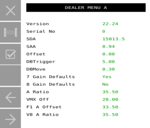
| Item | Options | Explanation | Range | Default Setting |
| Version | Current version of the software. | V24p00 | ||
| Serial No | Serial number of the instrument. | 0 to 9999 | 0000 | |
| System Delay Air (SDA) | Last air reading delay measurement. | R/O (pS) | 027,000.0 | |
| System Attn. Air (SAA) | Last air reading attenuation measurement. | R/O (dB) | 23.00 | |
| Offset | Adds any required bias to the moisture readings (leave at zero for best accuracy). | -99.99 to 99.99 | 00.00 | |
| DB Trigger | This value determines if a hay bale is present and triggers the start of the analysis process (uses half this value if low moisture levels are detected to increase bale detection sensitivity). | 0.0 to 99.9 | 05.00 | |
| DB Move | Change in attenuation to define bale movement (uses half this value if low moisture levels are detected to increase bale movement sensitivity). | 0.0 to 10.0 | 00.30 | |
| 7 Gain Def | Yes / No | Sets the gains to defaults on power up. | No | |
| 8 Gain Def | Yes / No | Sets the gains defaults on power up. | No | |
| 9 Gain Def | Yes / No | Sets the gains defaults on power up. | No | |
| 7 A Ratio * | T2/T1 ratio (module specific, internal value). | 00.0 to 40.0 | 35.30 | |
| 7 VMX Off * | Microwave module internal attenuation offset (module specific, internal value). | -99.90 to 99.99 | 28.00 | |
| 7 F1 A Off * | Value of the internal F1 attenuator used (module specific, internal value). | 0 to 40 | 33.50 | |
| 8 A Ratio * | T2/T1 ratio (module specific, internal value). Read from board. | 0 to 40.0 | R/O | |
| 8 VMX Off * | Microwave module internal attenuation offset (module specific, internal value). Read from board. | -99.90 to 99.99 | R/O | |
| 8 F1 A Off * | Value of the internal F1 attenuator used (module specific, internal value). Read from board. | 0 to 40 | R/O | |
| 9 A Ratio * | T2/T1 ratio (module specific, internal value). Read from board. | 0 to 40.0 | R/O | |
| 9 VMX Off * | Microwave module internal attenuation offset (module specific, internal value). Read from board. | -99.90 to 99.99 | R/O | |
| 9 F1 A Off * | Value of the internal F1 attenuator used (module specific, internal value). Read from board. | 0 to 40 | R/O | |
| Bale Drop | ISObus | This enables the Gazeeka to use the bale detected limit switch at the end of the bale chute to stop microwave reading of bale gaps and to determine the average and peak moisture per bale. | ISObus | |
| Bale on Chute | ISObus | If on power up the Krone ISObus is detected, make this “ISObus”. On an AGCO baler with or without ISObus this may be used with a bale on chute switch that we put in. | ISObus | |
| SWPPM | Number of pulses per metre of hay bale movement from the star wheel rotary encoder. | 0.0 to 9999.0 | 1000 | |
| 12V Limit | Lower limit for the measurement of microwaves (0.0 = don’t do test – set to 12). | 0.0 to 15.0 | 11.0 | |
| CAN Trace | On/Off | Records CAN messages for development. | Off | |
| Enter 123 to Reset | N/A | Resets all parameters to default values – AUTHORISED EMERGENCY USE ONLY | N/A |
* These values are written on the front of each Microwave Module. If the system is running a V8 or V9 ensure the values you see in the Dealer Menu match what is printed on the sticker on the Microwave Module (bottom board, left-hand side antenna).